9Products


Globe Type Control Valves — Precise Flow, Pressure, Temperature, and Level Regulation in PID Loops
In process engineering, there is a fundamental difference between an isolation valve — which simply opens or closes to allow or block flow — and a control valve — which continuously and proportionally regulates fluid flow to maintain a process variable (temperature, pressure, level, or flow rate) at the setpoint defined by the control system. This difference is not merely functional: it is in design, manufacturing precision, hydraulic characteristics, and integration capability with the control system.
Cematic control valves are complete instrumentation assemblies: process globe body, control trim sized with a Cv coefficient calculated for the specific process, pneumatic diaphragm actuator, and HART digital positioner — all assembled, calibrated, and documented in a single supply. The instrumentation engineer receives the complete assembly with the instrument data sheet (IDS), actuator torque curve, leak test certificate, and positioner configuration validated for their control system's signals.
Why is a control valve not the same as a ball or butterfly valve with a positioner?
This is the most frequent question from engineers evaluating whether to use a globe control valve or a segmented ball valve with a positioner. The answer has several technical dimensions:
- Inherent Flow Characteristic: The globe control valve has a flow characteristic precisely defined by the trim profile (plug and seat): linear or equal percentage. This means that the relationship between the disc position and the flow rate follows a predictable and reproducible mathematical curve, allowing the control engineer to design and tune the PID loop accurately. A standard ball valve has a quick-opening characteristic (flow rate increases rapidly in the first few degrees and then stabilizes), which makes precise control difficult at low opening positions.
- Rangeability: A globe control valve has a rangeability (ratio between maximum and minimum controllable flow) of 50:1 to 100:1 with standard trim. This means it can precisely control from 1% to 100% of its maximum flow capacity. A standard ball valve rarely exceeds 10:1 effective rangeability for control.
- Seat Leakage Class: Globe control valves are specified with ANSI/FCI 70-2 leakage classes ranging from Class II to Class VI, depending on the trim design. For applications where tight shutoff is critical (hazardous fluids, high-pressure steam), a high-tightness trim (Class V or VI) is specified, ensuring minimal or no leakage in the closed position.
- Design for Turbulent Flow and High Differential Pressure: The globe valve trim is designed to handle the kinetic energy of the fluid under high differential pressure conditions without premature erosion — a condition that would quickly destroy the seat of a conventional ball valve.
- Specialized Trim Capability: For fluids with solids, viscous fluids, cavitation services, erosive fluids, or corrosive fluids, specialized trims (anti-cavitation, anti-noise, low exit velocity) allow the globe valve to operate under conditions where any other valve would fail. These trim options do not exist in quarter-turn valves.
Types of Control Valves Available from Cematic
2-Way Globe Control Valve — The Process Control Standard
The 2-way globe valve has one inlet and one outlet. The plug moves linearly over the seat to vary the fluid passage area. It is the most universal configuration in process control: it controls the flow rate through a line in response to the controller's signal.
- Flow Over Seat (Under Plug): Fluid enters from below the seat and exits from above. This configuration causes the fluid pressure to assist the closing of the plug — less actuator torque required to keep the valve closed against process pressure. This is the standard configuration for most process control applications.
- Flow Under Seat (Over Plug): Fluid enters from above and exits from below. Fluid pressure assists the opening of the plug — more actuator torque required to close, but better anti-cavitation behavior in some fluids. Used when process conditions require it.
- Materials: Body in SS316 (CF8M) for corrosive, food, and pharmaceutical fluids; WCB for water, steam, oil, and general industrial fluids. Standard SS316 trim; Stellite 6 available upon request for erosive or high-temperature services.
- Connections: Flanged ANSI 150 and ANSI 300. Face-to-face according to ASME B16.10.
- Diameters: DN25 (1") to DN200 (8") in the most demanded ranges. Larger sizes available upon request.
3-Way Globe Control Valve — Fluid Mixing and Diverting
The 3-way globe valve has one inlet and two outlets (diverting configuration) or two inlets and one outlet (mixing configuration). A single plug acts simultaneously on two seats — as it opens towards one, it proportionally closes towards the other. This allows mixing two fluids in controlled proportions or diverting flow between two alternative destinations with a single control device.
- Mixing Configuration: Two incoming fluids (e.g., cold water and hot water) are mixed in variable proportions before exiting through a single port. The plug position determines the proportion of each fluid contributing to the outgoing mixture. Classic application: temperature control in HVAC systems, mixing process fluids in chemical formulation.
- Diverting Configuration: One incoming fluid is distributed between two outlets in variable proportions. By moving the plug to one extreme, all fluid goes to outlet A; to the other extreme, all goes to outlet B; in intermediate positions, it is distributed proportionally. Classic application: heat exchanger bypass, diverting product between alternative tanks.
- Main Advantage: A single 3-way valve replaces two 2-way valves with their associated control loop, reducing instrumentation cost, installation complexity, and system maintenance points.
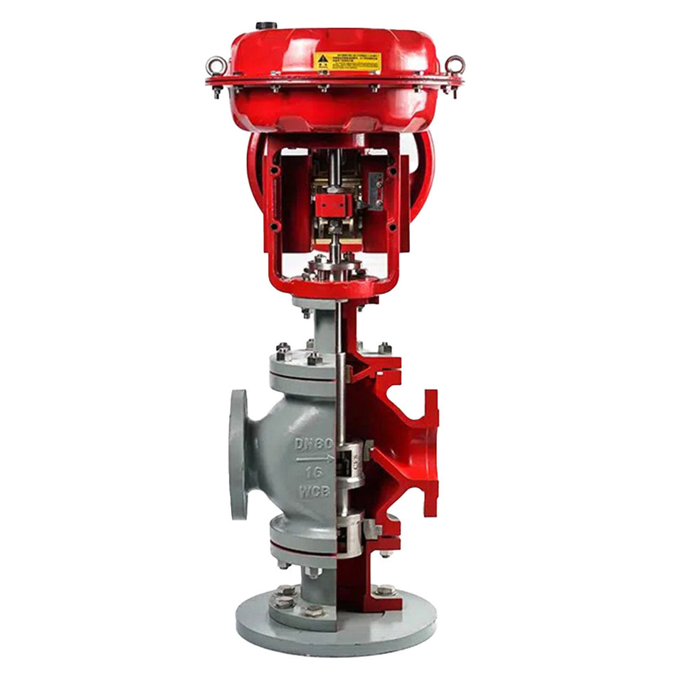
The Trim — The Technical Heart of the Control Valve
The trim of a control valve is the set of internal components that determine its hydraulic behavior: the plug, the seat, and the stem. It is the component that distinguishes a quality control valve from a generic process valve, and it is where most of the product's technical value lies:
- Parabolic Profile Plug (for linear characteristic): The parabolic profile of the plug is precisely machined so that the flow area increases linearly with stem travel — at 50% travel, 50% of the maximum Cv corresponds. Ideal for loops where process gain is constant throughout the entire operating range.
- Exponential Profile Plug (for equal percentage characteristic): For each equal increment of stem position, the same percentage increment in flow rate corresponds to the current flow rate — not an equal absolute increment. This means that control sensitivity is low at low opening positions (where the process error is small) and high at high positions (where the control margin is wide). The equal percentage characteristic is most used in temperature and pressure control.
- Cage Trim: The plug moves within a perforated cylindrical cage that defines the flow area by the number of exposed orifices. The cage design offers greater plug stability (no vibrations from turbulent flow), greater tightness in the closed position (the plug seats against the cage, not against a fixed seat), and ease of maintenance (the cage is interchangeable without welding or machining). It is the preferred trim in high differential pressure processes and critical services.
- Anti-Cavitation Trim: For liquid fluids with high differential pressure where static pressure drops below the liquid's vapor pressure, generating vapor bubbles that violently collapse when pressure recovers downstream — cavitation. The anti-cavitation trim reduces the pressure drop in multiple stages so that the pressure never falls below the vapor pressure at any point in the trim, eliminating cavitation and the erosive damage it causes.
- Anti-Noise Trim: For gases or vapors at high differential pressure where rapid expansion generates excessive aerodynamic noise (above 85 dBA in the downstream piping). The anti-noise trim divides the flow into multiple parallel small-diameter paths, reducing exit velocity and generated noise level. Required in applications where environmental or safety regulations establish noise limits in the installation.
Cv Coefficient — The Measure of Valve Flow Capacity
The Cv coefficient (or Kv in the metric system) is the fundamental parameter that defines the flow capacity of a control valve: numerically, it is the flow rate in gallons per minute (GPM) of water at 60 °F that passes through the fully open valve with a pressure drop of 1 psi. Correct Cv sizing is the most important engineering calculation in selecting a control valve:
- An oversized valve (Cv too large) always operates at low opening positions (less than 20%), where the non-linear relationship between position and flow makes PID control difficult, and where any small stem movement generates large flow changes — the loop oscillates and cannot stabilize.
- An undersized valve (Cv too small) cannot pass the required flow, always operates close to 100% opening, and has no control margin — the controller saturates the signal and loses regulation capability.
- The correct Cv positions the valve between 20% and 80% opening under normal operating conditions, with margin at both ends to handle variations in process demand.
At Cematic, we perform the Cv calculation using process data (design flow rate, inlet and outlet pressure, temperature, fluid density) at no additional cost when quoting.
Calculate your control valve Cv online — Cematic free tool
For applications with liquid fluids, gases, or steam under standard conditions, you can immediately obtain the recommended Cv with our online Cv calculator: enter the flow rate, inlet and outlet pressures, temperature, and fluid type, and the tool calculates the design Cv, the recommended installed Cv with safety factor, and the suggested valve size — in seconds, without the need for tables or specialized software.
👉 Use the Free Cv Calculator →
For processes with non-standard fluid properties (mixtures, non-Newtonian fluids, critical cavitation or flash conditions), high differential pressure conditions, or specialized trim requirements (anti-cavitation, anti-noise, Class V or VI), our instrumentation team performs the complete calculation according to ISA 75.01 with the included instrument data sheet — at no additional cost for projects under evaluation. Share your process data via WhatsApp or email to ventas@cematic.com.
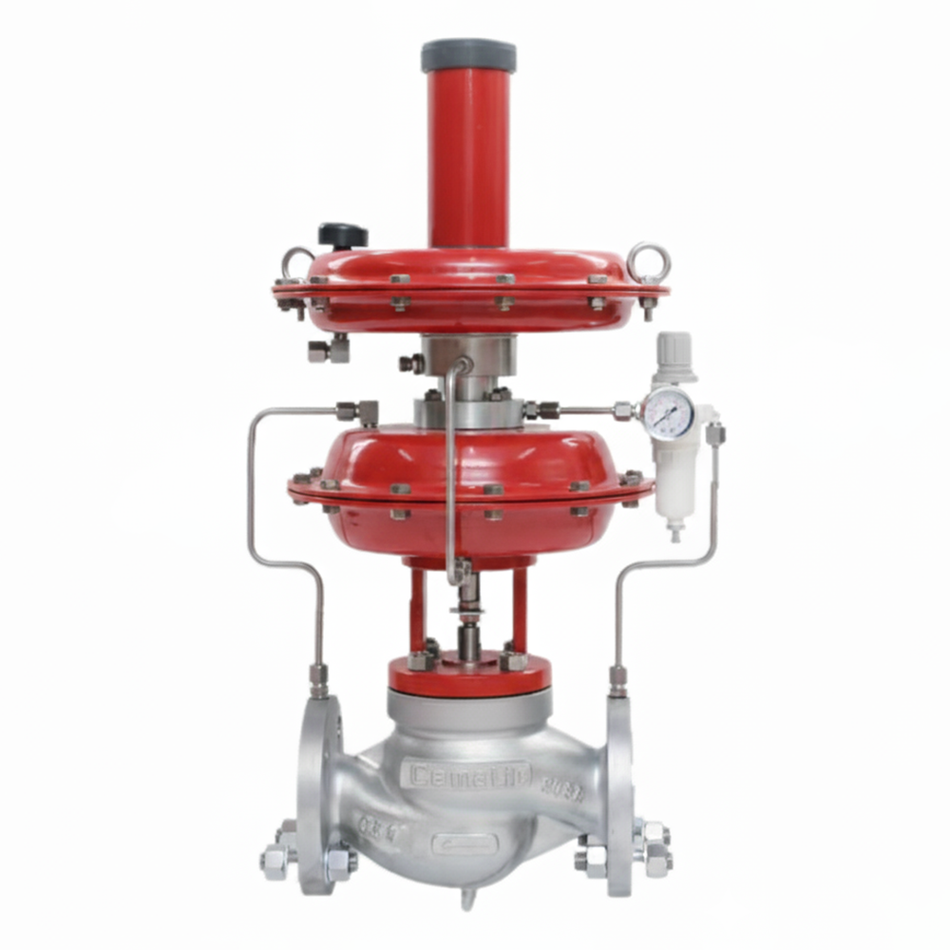
Pneumatic Diaphragm Actuator — The Standard Actuation for Globe Control Valves
Unlike ball and butterfly valves that use rack-and-pinion actuators (rotational movement), globe control valves use diaphragm actuators (linear movement) for two fundamental technical reasons:
- Direct Linear Motion: The globe valve stem moves linearly — the diaphragm actuator applies its force directly in the same direction without the need for rotation→translation conversion. This directness eliminates mechanical play that would cause hysteresis and positioning inaccuracy.
- Smooth Movement: The rubber diaphragm (EPDM or NBR) has no seal friction like a piston — its movement is perfectly smooth and linear with air pressure, allowing the positioner extremely precise position control without stick-slip (jerky movement).
The Cematic diaphragm actuator is a single-acting, spring-return type (spring-and-diaphragm), the worldwide standard configuration in process control:
- Air-to-Open (ATO) / Fail-Close: Air opens the valve against the spring. Upon loss of air supply, the spring closes the valve — fail-safe position CLOSED. The most frequent in process control.
- Air-to-Close (ATC) / Fail-Open: Air closes the valve against the spring. Upon loss of air supply, the spring opens the valve — fail-safe position OPEN. For services where failure must maintain flow (reactor cooling, equipment lubrication).
HART Digital Positioner — Integration with the Control System
All Cematic control valves are supplied with an integrated digital positioner with HART protocol. The positioner is the device that closes the position loop between the controller's signal and the actual stem position:
- The DCS or PLC's PID controller sends the position setpoint signal (4–20 mA — where 4 mA = valve closed, 20 mA = valve fully open)
- The positioner measures the actual stem position using a non-contact Hall effect sensor (no friction, no wear)
- Calculates the error between setpoint and actual position
- Adjusts the air pressure to the actuator to move the stem to the exact required position
- Automatically corrects any deviation caused by process pressure variations, stem friction, or temperature changes
The superimposed HART protocol over the 4–20 mA loop simultaneously allows conventional analog control and bidirectional digital communication for:
- Remote configuration and calibration without opening the positioner's housing — from any HART communicator or asset management system (AMS, PACTware, FieldCare)
- Real-time diagnostics reading: position, air supply pressure, response time, valve signature
- Automatic Auto-Setup in less than 60 seconds — complete calibration without additional tools
- Partial Stroke Test (PST) function to verify ESD valve functionality without interrupting the process
- Cycle history, cumulative deviation, and predictive wear diagnostics
General Technical Specifications
- Valve Type: Linear motion globe control, 2-way and 3-way
- Body Material: Stainless Steel CF8M (ASTM A351 — equivalent SS316) or Carbon Steel WCB (ASTM A216)
- Standard Trim Material: Stainless Steel SS316; Stellite 6 upon request for erosion or high-temperature services
- Pressure Classes: ANSI 150 (up to 19.6 bar at ambient temperature) and ANSI 300 (up to 50 bar at ambient temperature)
- Nominal Diameters: DN25 (1") to DN200 (8") — other diameters upon request
- Operating Temperature: -29 °C to +230 °C with standard PTFE packing; up to +425 °C with graphite packing in high-temperature models
- Trim Flow Characteristics: Linear or Equal Percentage — specify according to the control loop
- Standard Leakage Class: ANSI/FCI 70-2 Class IV (leakage ≤ 0.01% of maximum Cv). Class V and Class VI available upon request.
- Design Standards: ASME B16.34 (pressure-temperature), ASME B16.10 (face-to-face), ISA 75.01 (control valve sizing)
- Testing Standards: IEC 60534-4 (leak test), ANSI/FCI 70-2 (leakage class)
- Positioner Signal: 4–20 mA input with superimposed HART; 4–20 mA feedback of actual position
- Actuator Supply Pressure: 1.4 to 4.0 bar (diaphragm actuator) — lower than standard pneumatic rack-and-pinion actuator
Sizing — The Data Needed for Quoting
Unlike isolation valves that are selected only by diameter and pressure class, a control valve requires a complete sizing calculation to correctly specify the Cv, trim, actuator, and positioner. To quote, Cematic needs:
- Fluid: Name, phase (liquid, gas, steam), process temperature
- Design Flow Conditions: Normal flow and maximum required flow (in m³/h, kg/h, or process units)
- Inlet Pressure (P1): Upstream pressure of the valve under normal and maximum conditions
- Outlet Pressure (P2): Downstream pressure of the valve — the difference P1-P2 is the differential pressure for calculation
- Specific gravity or fluid density at process temperature
- Fail-Safe Position: Fail-Open (ATC) or Fail-Close (ATO)
- Required Flow Characteristic: Linear or Equal percentage (or indicate the type of control loop for technical recommendation)
- Required Leakage Class: IV standard, V or VI for critical applications
- Project Standards: If the project has its own engineering specifications (customer IDS, corporate standards)
Our instrumentation team calculates Cv according to ISA 75.01, verifies the correct trim for the fluid and process conditions, and issues the Instrument Data Sheet (Valve Data Sheet) with the complete technical specification of the selected valve — at no additional cost for projects under evaluation.
Main industries and applications
- Chemical and petrochemical industry: Temperature control in reactors using heating steam or cooling water valves in the jacket, pressure regulation in distillation columns, flow control of reactants in synthesis lines. The 3-way globe valve for mixing is the standard for temperature control of reactors with exchanger bypass.
- Power generation and cogeneration: Process steam control in exchangers and cogeneration turbines, boiler feedwater regulation, condensate temperature control. The WCB ANSI 300 globe valve with Stellite trim is the standard for high-pressure and high-temperature steam in these systems.
- Food and pharmaceutical industry: Pasteurization temperature control, steam regulation in autoclaves and sterilizers, ingredient flow control in dosing lines. SS316 valves with PTFE packing and ANSI 150 flanged connections.
- Industrial HVAC and climate control systems: 3-way globe valves for mixing and diverting hot water and chilled water in HVAC systems for large industrial and commercial facilities. Proportional control via a 4–20 mA signal from the BMS allows fine adjustment of the supply air temperature to the AHU or FCU.
- Industrial water treatment: Flow control of treatment reagents (coagulants, flocculants, pH adjusters) in process water and boiler treatment plants. The precision of the control loop with a globe valve is crucial for the quality of the treated water and the efficient consumption of reagents.
- Oil and gas: Control valves for injecting corrosion inhibitors and demulsifiers in production facilities, pressure control in gas regulation stations, flow regulation in metering lines. WCB ANSI 300 version for high-pressure services.
- Pulp and paper: Temperature control in kraft digesters using high-pressure steam globe valves, pulp consistency regulation with 3-way valves for mixing pulp and dilution water, temperature control in bleach plants.
The Cematic difference in control valve supply
A control valve is not a standard catalog product — each application requires specific sizing and a trim configuration appropriate to the fluid and process conditions. At Cematic, we offer a complete technical selection process:
- ✅ Cv calculation with customer process data according to ISA 75.01
- ✅ Trim selection (plug profile, material, leakage class) for the specific fluid and conditions
- ✅ Actuator sizing with required force calculation and torque verification at available supply pressure
- ✅ Positioner configuration for the control signals of the client's specific system (4–20 mA, HART, ATO/ATC)
- ✅ Instrument Data Sheet (IDS) with complete technical specification according to ISA or project format
- ✅ Test certificate for tightness, hydrostatic body test, and actuator torque curve
- ✅ Formal technical quotation with detailed specification on the same business day for projects with complete process data
Contact us via WhatsApp or at ventas@cematic.com with your application's process data and receive the complete technical specification of the correct control valve for your loop on the same business day.