7Products


Cematic Quarter-Turn Electric Actuators — Complete Range from 35 to 4,500 Nm with IP67 Protection and CE Certification
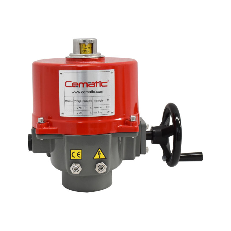
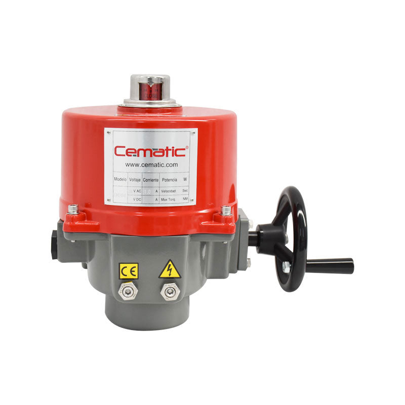
Cematic quarter-turn electric actuators are the valve automation solution for installations where compressed air is not available or where direct digital integration with the control system is a priority. The entire range shares the same design philosophy: anodized aluminum housing with C3 corrosion category epoxy paint (ISO 12944-2), high-alloy steel gears with a self-locking system that eliminates backlash, integrated thermal protection in the motor, continuous mechanical position indicator visible from any angle, and clutchless manual override that allows the valve to be operated by hand during electric service without risk of accident.
The range covers from the most compact model—35 Nm with override lever, for small diameter ball valves—to the highest torque model available—4,500 Nm with override handwheel, for large diameter butterfly valves in water infrastructure and heavy industrial processes. All models are CE and CSA certified, and conform to the ISO 5211 mounting interface, guaranteeing direct compatibility with ball and butterfly valves from all manufacturers on the market.
Construction features common to the entire range
- Housing: Aluminum alloy with epoxy polyester paint finish. C3 corrosion category according to ISO 12944-2 standard; C4 and C5 available upon request for marine or aggressive industrial environments. SS316 stainless steel housing option available on models OM-1 to OM-6, OM-F, and OM-G with IP68 protection.
- Protection: NEMA 4X, NEMA 5 and IP67 standard — resistant to dust, rain, and temporary immersion up to 1 meter for 30 minutes. Suitable for outdoor installation without additional protection. IP68 option at 7 meters / 72 hours available on selected models.
- Gear System: High-alloy steel gears with permanent factory lubrication. Self-locking system that prevents position rollback due to vibration or differential valve pressure — no additional brake needed. No backlash in the transmission.
- Motor: Class F insulation standard; class H available as an option. Integrated thermal protection that automatically cuts off the motor before it reaches damaging temperatures: 125 ±5 °C for AC motors and 90 ±5 °C for DC motors. Thermal protection automatically resets when the motor cools down without manual intervention.
- Duty Cycle: 30% standard across the entire range. Option for extended cycle to 75% (models OM-A, OM-AM, OM-1 to OM-8 and OM-H) or 50% (models OM-9 to OM-13) using an extended IEC motor kit available upon request.
- Position Indicator: Continuous mechanical position indicator visible from the top of the actuator. The actual valve position is readable at any point of the travel from 0° to 90° without additional instrumentation.
- Operating Temperature: -30 °C to +65 °C standard. Relative operating humidity: 30% to 95%.
- Valve Interface: ISO 5211 on all models — guaranteed compatibility with ball and butterfly valves from any manufacturer meeting the standard.
- Adjustable Mechanical Stops: Available on models OM-2 to OM-13, OM-F, OM-G, and OM-H. They prevent valve overtravel at both ends of the stroke and allow adjustment of the actual opening and closing angles in the field.
- Clutchless Manual Override: The handwheel or manual operating lever can be operated directly without needing to disconnect or engage a clutch. During motor operation, the handwheel does not rotate for operator safety — protection against unexpected rotation of the crank while the actuator is energized.
Available Models — Torque, Weight, and ISO 5211 Interface
| Model | Torque (Nm) | Torque (in-lb) | Weight (kg) | 90° Time (sec) | Manual Override | ISO 5211 Interface |
|---|---|---|---|---|---|---|
| OM-1 | 35 | 310 | 2 | 12 | Lever | F03 / F05 |
| OM-A | 50 | 445 | 3 | 27 | N/A | F05 / F07 |
| OM-AM | 50 | 445 | 3 | 27 | Lever | F05 / F07 |
| OM-F | 65 | 575 | 11 | 6 | Handwheel | F07 / F10 |
| OM-J | 80 | 708 | 3 | 130 | Lever | F05 / F07 |
| OM-2 | 90 | 800 | 10.5 | 17 | Handwheel | F07 / F10 |
| BM-2 | 120 | 1,065 | 5.5 | 9 | N/A | F07 |
| OM-G | 120 | 1,065 | 11 | 8 | Handwheel | F07 / F10 |
| OM-3 | 150 | 1,330 | 10.5 | 26 | Handwheel | F07 / F10 |
| OM-H | 300 | 2,655 | 15 | 24 | Handwheel | F07 / F10 |
| OM-4 | 400 | 3,540 | 20 | 19 | Handwheel | F10 / F12 |
| OM-5 | 500 | 4,430 | 20 | 26 | Handwheel | F10 / F12 |
| OM-6 | 650 | 5,755 | 20 | 34 | Handwheel | F10 / F12 |
| OM-7 | 1,000 | 8,855 | 36 | 50 | Handwheel | F12 or F14 |
| OM-8 | 1,500 | 13,280 | 36 | 51 | Handwheel | F12 or F14 |
| OM-9 | 2,000 | 17,710 | 68.5 | 62 | Handwheel | F14 or F16 |
| OM-10 | 2,500 | 22,140 | 68.5 | 62 | Handwheel | F14 or F16 |
| OM-11 | 3,000 | 26,565 | 68.5 | 62 | Handwheel | F14 or F16 |
| OM-12 | 3,500 | 31,000 | 68.5 | 62 | Handwheel | F14 or F16 |
| OM-13 | 4,500 | 40,000 | 102.5 | 88 | Handwheel | F16 / F25 |
Motor power and travel time data based on 110 V AC / 60 Hz / 30% duty cycle / floating control.
Power Supply Voltages Available per Model
The Cematic range covers all electrical supplies available in the Mexican industry:
- 12 VDC: Available in OM-1, OM-A, OM-AM, OM-H, and OM-2 to OM-10. For power from batteries, solar panels, and backup systems in remote locations.
- 24 VDC: Available in the entire range except BM-2 and OM-J. The universal standard for modern PLCs: Allen-Bradley, Siemens S7, Mitsubishi MELSEC, and all contemporary automation platforms. Direct connection from PLC digital output without additional power relay.
- 24 VAC: Available in OM-1, OM-A, OM-AM, OM-F, OM-G, OM-H, and OM-2 to OM-10.
- 110–120 VAC Single-Phase: Available across the entire range. The most common mains voltage in industrial panels in Mexico (120 V / 60 Hz). No low voltage transformer needed.
- 220–240 VAC Single-Phase: Available across the entire range. For installations with two-phase industrial power or where distance to the panel would cause unacceptable voltage drop at 110 V.
- 220–240 VAC Three-Phase: Available in BM-2, OM-F, OM-G, OM-H, and OM-2 to OM-13. For higher torque actuators where the three-phase motor offers better efficiency and lower starting current than the equivalent single-phase motor.
- 380–415 VAC Three-Phase: Available in BM-2, OM-F, OM-G, OM-H, and OM-2 to OM-13.
- 440–480 VAC Three-Phase: Available in BM-2, OM-F, OM-G, OM-H, and OM-2 to OM-13. For installations with high-voltage industrial supply in the US or Mexican installations with this standard.
Other voltages available upon request: 125 VDC, 208 VAC three-phase, 575 VAC three-phase. Inquire.
Operating Modes and Control Signals
ON/OFF Control (Full Open and Close)
The valve operates exclusively between 0° (closed) and 90° (open). The actuator receives a digital signal from the control system and completes the full stroke to the mechanical stop, where integrated torque protection automatically stops the motor. Two integrated limit switches (LS1 for fully open position, LS2 for fully closed position) provide feedback to the PLC confirming that the valve completed its movement. Two additional auxiliary limit switches (LS3 and LS4) are available as an option for intermediate signaling functions.
Floating Control
Floating mode uses two independent digital signals — one for "open" and one for "close" — that keep the motor running while the signal is active and stop it when deactivated. It allows positioning at any intermediate point between 0° and 90° by controlling the activation time of each signal. This is the standard mode for most models in the range and the basis for the power and time data in the technical table.
Modulating Control — 4–20 mA / 1–5 V / 2–10 V Signal
The optional modulating control unit converts the actuator into a proportional positioning device: the valve position continuously and proportionally follows the analog signal from the PID controller. At 4 mA the valve is at 0°; at 20 mA it is at 90°; intermediate values position the valve proportionally with ±1–2% accuracy of the full range. The analog position feedback signal — 4–20 mA or 2–10 V output — confirms the actual position to the controller in real time, closing the control loop. Analog inputs accepted: 4–20 mA, 1–5 V, and 2–10 V.
Modbus RTU Communication (RS-485)
Available as an option in models OM-1, OM-A, OM-AM, OM-H, and OM-2 to OM-8 (110–120 V AC / 1PH, 30% duty cycle) and OM-2 to OM-8, OM-F, OM-G, and OM-H (220–240 V AC / 1PH, 30% duty cycle). The Modbus RTU protocol over RS-485 allows direct integration with SCADA, DCS, and PLCs with a serial port or Modbus communication module. Up to 32 actuators can be connected in a daisy chain over a single RS-485 cable pair. The control system can read and write: position setpoint, actual position, alarm status, motor temperature, and accumulated cycle count.
Available Options and Accessories
Anti-Condensation — Heating Resistor
Internal electric resistor that raises the internal temperature of the actuator to prevent lubricant freezing and keep the interior dry in environments with high temperature variations between day and night or between seasons. Not recommended if ambient temperature continuously exceeds 35 °C. It is recommended to combine with the heater thermostat (see below) when the temperature varies significantly.
Heater Thermostat
Automatically disconnects the heating resistor when the internal temperature of the actuator exceeds 25 ±5 °C, preventing unnecessary overheating of the actuator and reducing the electrical consumption of the resistor.
Thermal Insulation Blanket
Allows actuator operation after prolonged exposure to high temperatures in the installation environment. Validated working conditions: exposure to 250 °C for 2 hours or exposure to 300 °C for 1 hour. Its jacket-type design allows quick installation and removal without tools. Available for models OM-A, OM-AM, and OM-1 to OM-8 in ON/OFF or floating control.
Feedback Potentiometer
Resistive position transducer (1 kΩ or 5 kΩ selectable) for use with floating control actuators that require position feedback for remote indication or SCADA system logging. Recommended when floating mode is preferred over modulating but continuous position indication is needed.
Analog Position Output
Analog output module that converts the actual actuator position into a standard process signal: 0–20 mA, 4–20 mA, 0–5 V, 0–10 V, 1–5 V, or 2–10 V selectable. Allows integration of the floating control actuator into DCS or SCADA monitoring loops without upgrading the control mode to modulating.
Time Delay Controller
Allows configuring a time delay between receiving the control signal and the start of actuator movement. Configuration range: up to 200 s, 300 s, or 600 s depending on the selected jumper, with 10 adjustment positions via dip switch. Available for OM-2 to OM-13 at 220 VAC and OM-2 to OM-8 at 110 VAC. Useful in sequencing systems where multiple valves must open or close in order, without the need for additional PLC logic.
Torque Switches
Provides additional protection against operating overtorque — the actuator automatically stops if the required torque exceeds the set threshold, protecting both the actuator and the valve from damage due to mechanical obstruction or a stuck valve. Must be specified and configured at the factory — not field installable. Available for OM-2 to OM-13, OM-F, OM-G, and OM-H.
Local Control Unit (LCU)
Adds two rotary selectors to the actuator for manual field operation: LOCAL/REMOTE and CLOSE/STOP/OPEN. In LOCAL mode, the valve is operated directly from the field by the operator without a signal from the central control system. Standard IP65 protection; IP67 and NEMA 4X available as an option. Available for all models in the range.
External Junction Box
Allows external electrical connections without removing the actuator cover, simplifying field installation and maintenance. Especially useful for actuators installed in hard-to-reach areas or where the actuator's IP protection must be maintained during connection operations.
Chain Wheel Drive
For manual operation in elevated or hard-to-reach positions using a hanging chain. The operator pulls the sprocket chain to operate the valve from the ground without the need for scaffolding or a ladder. Available for OM-2 to OM-13, OM-F, OM-G, and OM-H.
Extended Travel
Standard: 0° to 90°. Option for extended rotation angle up to 270° for plug valve applications, angular regulators, or any valve requiring travel greater than the standard quarter-turn. Available for OM-1 to OM-8 and OM-H.
Isolation Relay Module
When a single control switch operates two or more actuators simultaneously, the isolation module prevents electrical interference between the circuits. Available for OM-2 to OM-8, OM-F, and OM-G.
Available Certifications
Standard Models (Unclassified Area)
- CE — all models except BM-2
- CSA — all models except BM-2
- UKCA — all models except BM-2
- RoHS and REACH — environmental compliance in materials
- ISO 9001, ISO 14001, ISO 45001 — manufacturer's management system
Versions for Classified Areas (Potentially Explosive Atmospheres)
For installations in areas with flammable gases (Zone 1 / Zone 2) or combustible dusts (Zone 21 / Zone 22), we offer versions with explosion-proof housings certified under applicable international regulations:
- ATEX II 2GD — Ex db IIB T4 Gb / Ex tb IIIC T130°C Db — for the European Union. Standards EN IEC 60079-0, EN 60079-1, EN 60079-31.
- IECEx — same marking as ATEX for the international market. Standards IEC 60079-0, IEC 60079-1, IEC 60079-31.
- CSA — North American Hazardous Areas — Zone System (Class I Zone 1 / Class II Zone 21) and Division System (Class I Division 1 Groups C,D / Class II Division 1 Groups E,F,G). Temperature: T4 for gases, T130°C for dusts. Ambient temperature range: -30 °C to +70 °C.
- UKCA Hazardous Areas — for Great Britain. Same marking as ATEX.
Ambient temperature for all classified zone versions: -30 °C to +70 °C.
Model Selection Guide by Application
| Typical Application | Valve | Estimated Torque | Recommended Model | ISO 5211 |
|---|---|---|---|---|
| Ball valve ½"–1" NPT thread, water / air | SS316 Ball DN15–DN25 | 10–25 Nm | OM-1 (35 Nm) | F03/F05 |
| Ball valve 1"–2" NPT thread, general process | SS316 Ball DN25–DN50 | 25–60 Nm | OM-A / OM-AM (50 Nm) | F05/F07 |
| Ball valve / butterfly valve 2"–3", process | Ball or butterfly DN50–DN80 | 60–120 Nm | OM-2 / OM-G (90–120 Nm) | F07/F10 |
| Butterfly valve 3"–4", water / HVAC | Cast iron butterfly DN80–DN100 | 120–200 Nm | OM-3 / OM-H (150–300 Nm) | F07/F10 |
| Butterfly valve 6"–8", water plant | Cast iron butterfly DN150–DN200 | 300–600 Nm | OM-4 / OM-5 (400–500 Nm) | F10/F12 |
| Butterfly valve 10"–12", industrial process | Butterfly DN250–DN300 | 600–1,200 Nm | OM-6 / OM-7 (650–1,000 Nm) | F10/F12/F14 |
| Butterfly valve 14"–16", water infrastructure | Butterfly DN350–DN400 | 1,200–2,000 Nm |