12Products

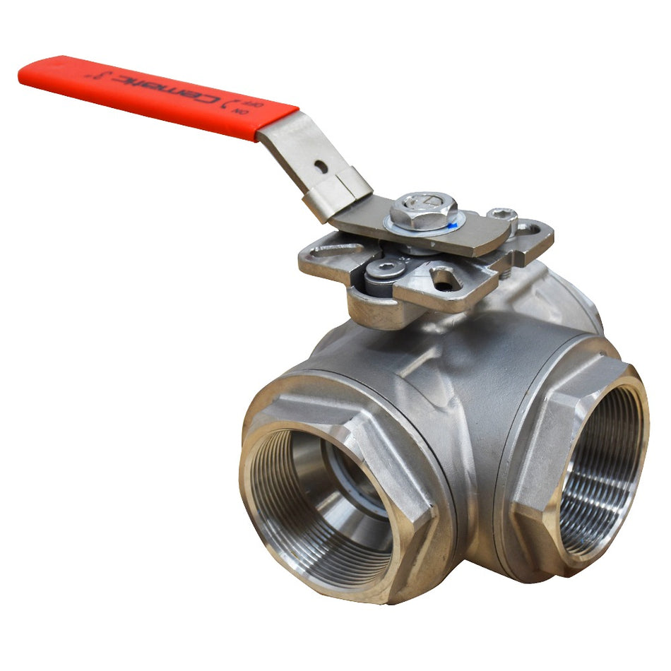


3-Way Ball Valves — L-Port and T-Port for Fluid Diversion, Selection, and Mixing with a Single Valve
A 3-way ball valve has exactly what its name suggests: three pipe connections on the valve body instead of the usual two. The internal ball has a bore that, depending on its design (L-port or T-port), allows different combinations of the three ports to be connected by rotating 90° or 180°. The practical result is that a single valve can do what would normally require two coordinated 2-way valves: select between two supply sources, divert flow between two destinations, mix two fluid streams, or isolate equipment while maintaining flow in the main circuit.
The economic and operational advantage of the 3-way valve over two coordinated 2-way valves is clear: a single valve instead of two, a single maintenance point instead of two, a single actuator instead of two (when automated), and a more compact installation with fewer flanged or threaded connections — each additional joint is a potential leak point. In processes where the cost of each control point is relevant and installation space is limited, the 3-way valve is the solution that simultaneously optimizes cost, compactness, and reliability.
L-Port vs. T-Port — the difference that determines everything
This is the most important technical decision when specifying a 3-way ball valve. The L-port and T-port behave completely differently with the same actuator positions — specifying the incorrect one will result in a valve that does not perform the required function:
L-Port — Diversion between Two Destinations or Selection between Two Sources
The L-port ball has an L-shaped bore — a channel that rotates 90° inside the ball. It always connects only two of the three ports, never all three simultaneously. By rotating the ball 90°, it changes which two ports are connected.
Visualizing the three valve ports as A (top or main inlet), B (left side), and C (right side or alternative outlet):
- 0° Position: The L-bore connects A to B — fluid enters through A and exits through B. Port C is blocked.
- 90° Position: The L-bore connects A to C — fluid enters through A and exits through C. Port B is blocked.
- There is no position where all three ports are connected simultaneously with an L-port ball.
When to use L-port:
- Flow diversion between two alternative destinations — "send this batch to tank A or tank B"
- Selection between two supply sources — "feed the equipment from source 1 or source 2"
- Equipment bypass — "send the fluid through the equipment or through the direct bypass"
- Emergency dual-feed systems — normally connected to the main source, in an emergency it switches to the backup source
T-Port — Mixing, Simultaneous Distribution, or Total Isolation
The T-port ball has a T-shaped bore — a main straight channel plus a perpendicular branch at 90°. It can connect all three ports simultaneously (in the central position) or only two of them (in extreme positions).
Visualizing the three ports as A (inlet), B (outlet 1), and C (outlet 2):
- 0° Position (central position): The T-channel connects A, B, and C simultaneously — fluid enters through A and can exit through B and C at the same time, or two fluid streams (A and C) mix and exit through B.
- 90° Position: The T-channel connects A to B only — fluid flows from A to B. Port C is blocked.
- -90° Position (or 270°): The T-channel connects A to C only — fluid flows from A to C. Port B is blocked.
When to use T-port:
- Mixing two fluid streams at one point — "mix hot and cold water before the point of use"
- Simultaneous distribution to two destinations — "distribute a fluid to two parallel pieces of equipment or close one of them"
- Recirculation systems — "send the fluid to the process or recirculate it to the source tank"
- Temperature control by mixing — "mix hot and cold fluid to achieve the desired temperature before the exchanger"
- Bypass with simultaneous operation capability — the T-port allows, in the central position, fluid to pass simultaneously through the equipment and through the bypass (useful during startups)
L-port vs. T-port comparison table
| Characteristic | L-Port | T-Port |
|---|---|---|
| Ports connected in 0° position | A–B only | A–B–C simultaneously |
| Ports connected in 90° position | A–C only | A–B only (or A–C at -90°) |
| Can all 3 ports be connected at once? | ❌ Never — only 2 ports in each position | ✅ Yes — in central position (0°) |
| Main function | Diversion or selection between alternatives | Mixing or simultaneous distribution |
| Actuator travel to change circuit | 90° rotation | 90° rotation |
| Can it completely isolate all ports? | ❌ Two ports are always connected | ❌ Two ports are always connected in extreme positions |
| Temperature mixing application | ❌ Not suitable — does not mix simultaneously | ✅ Ideal — mixes in central position |
| Simple bypass application | ✅ Ideal — sends all fluid to A or B | ⚠️ Possible — but connects simultaneously in central position |
Port orientation — the physical configuration
In addition to the ball type (L or T), the 3-way valve has different possible orientations of the three ports in the body — which determine how it is installed in the piping:
- L-configuration (two in-line ports + one side port): Two ports are in a straight line (like a conventional 2-way valve) and the third port exits perpendicular to the body. Most common in industrial installations — it is installed in a main line with a side branch.
- T-configuration (three ports at 120° or 90° each): The three ports are symmetrically distributed around the body. Less frequent in industrial process installations.
In most industrial 3-way valves on the market, the physical configuration is L-shaped (two in-line ports plus one side port) regardless of whether the ball is L-port or T-port — do not confuse the physical body configuration with the ball bore type.
Available materials
SS316 Stainless Steel — For Water, Chemical, and General Process
The most frequent choice for the process industry in Mexico. SS316 resists seawater, saline solutions, dilute acids, moderate alkalis, and most industrial aqueous fluids. Available with NPT threaded connections (½" to 2") and ANSI 150 flange (DN25 to DN100) with virgin PTFE seats.
WCB Carbon Steel — For Hydrocarbons, Gas, and Heavy Process
For natural gas, LPG, process oils, and hydrocarbon services where SS316 is not necessary for corrosion resistance but where ferrous material is the industry standard. Available with ANSI 150 and ANSI 300 flanges. PTFE seats with graphite for moderate temperature hydrocarbon service.
PVC — For Water and Low-Aggressiveness Chemicals
For installations where metal is not viable — reverse osmosis, swimming pools, aquaculture, chemicals with very dilute acids — the PVC 3-way valve with L-port or T-port covers the same diversion and mixing functions as metal valves. See PVC Ball Valves →
Technical specifications
- Available materials: SS316 (NPT thread and ANSI 150 flange), WCB (ANSI 150 and ANSI 300 flange)
- Ball: SS316 or chrome-plated carbon steel with L or T bore
- Seats: Virgin PTFE — two seats in each active port
- Stem packing: PTFE
- Ball configuration: L-port (diversion/selection) or T-port (mixing/distribution) — specify when ordering
- Connections: NPT thread (½" to 3") or ANSI 150/300 flange (DN25 to DN100)
- Nominal pressure: Up to PN64 for SS316 threaded; up to 19.6 bar for ANSI 150 flanged
- Temperature: -20 °C to +180 °C with PTFE seat
- Actuator travel: 90° between extreme positions (0° to 90°)
- Actuator mounting: ISO 5211 standard on all models
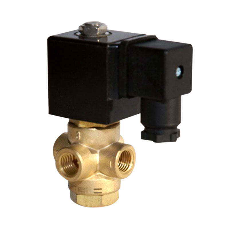
- Operation: Manual with lever or automated with pneumatic or electric actuator
Automation of the 3-way valve — specific considerations
The automation of a 3-way valve has peculiarities compared to the conventional 2-way valve that are important to know before specifying the control system:
Actuator travel — only 90°
The 3-way ball valve operates between its two extreme positions with only 90° of rotation — just like a 2-way valve. The same standard quarter-turn actuator (pneumatic or electric) that operates a 2-way valve can operate a 3-way valve of the same operating torque without modifications.
Pneumatic actuator — only double-acting or single-acting depending on the function
For the 3-way valve, the fail-safe position of the actuator is especially important because it defines which of the two circuits remains active in case of a control system failure:
- Single-acting: In case of air supply loss, the actuator moves the valve to the spring position — which corresponds to one of the two circuits (A→B or A→C depending on the actuator mounting position). Correct when there is a defined fail-safe position: "in an emergency, send the fluid to safety tank B, not to reactor A".
- Double-acting: In case of air supply loss, the valve maintains its last position (fail-last). Correct when the last position is the safe state for the process, or when there is no preferred fail position.
Intermediate position control — not recommended
Unlike the control globe valve, the 3-way ball valve should not be used for proportional mixing regulation in intermediate positions (between 0° and 90°). In an intermediate position, the PTFE ball scrapes the seats in each partial open/close cycle, generating accelerated wear that would destroy the seats in a few weeks. The 3-way valve is an ON/OFF component (position A or position B) — for proportional temperature or flow mixing, the correct solution is the 3-way control globe valve →
Feedback signal to the control system
The standard limit switch box provides two signals: one confirms that the valve is in position A (0°) and the other confirms position B (90°). The control system receives confirmation of which circuit is active at any given moment — critical information in systems where both circuits handle different fluids and a confusion can contaminate the process.
Most frequent applications
Process Equipment Bypass
The most common application of the 3-way ball valve in Mexican industry. A single valve replaces the traditional assembly of three 2-way valves in a bypass configuration: inlet valve, equipment outlet valve, and bypass valve. With the 3-way valve, the circuit is switched between "through the equipment" and "through the bypass" with a single 90° turn, from the control panel with the appropriate actuator.
Typical examples: bypass of cartridge filters (switch to backup filter while replacing the main filter cartridge), bypass of heat exchangers (maintain the process while servicing the exchanger), bypass of flow meters for calibration.
Supply Source Selection
Systems with a primary source and a backup source where switching between them must be instantaneous and reliable — without a period of supply interruption between the closing of one source and the opening of the other. The 3-way valve with an L-port instantly switches from one source to the other in the same 90° turn: when closing the connection with source A, it simultaneously opens the connection with source B, without interruption of flow.
Diversion between Storage Tanks
In batch production plants where the product from the same line must be directed to different storage tanks according to the batch, the 3-way valve with an L-port automates the selection of the destination tank from the recipe control system, without the need for two 2-way valves with their associated interlock logic.
Mixing Fluids at Controlled Temperature
T-port application — mixing hot and cold water in controlled temperature water distribution systems, mixing two process streams at fixed proportions (fully open on both inlets, single mixed outlet), heating systems with return mixing and boiler hot water. For proportional temperature mixing (PID control), see the 3-way control globe valve →
Distribution of Reagents to Multiple Points
Distribution of a reagent or process fluid to two alternative addition points — for example, pH adjustment acid that can be dosed at point A or point B of the process according to the operating stage. A 3-way valve with an L-port and pneumatic actuator solves this with a single component and a single control signal.
Recirculation vs. Process
In many industrial processes, startup requires recirculating the fluid to the source tank until it reaches the correct conditions (temperature, pH, density) before sending it to the main process. A 3-way valve with an L-port manages this selection: position A = recirculation to tank, position B = send to process. With a NC (normally closed to process) pneumatic actuator, the system ensures that during startup the fluid always recirculates until the control system authorizes sending to process.
HVAC Systems — Hot and Cold Water Mixing
The 3-way ball valve (T-port) with a modulating electric actuator is common in HVAC systems for mixing boiler hot water and cold return to maintain the supply temperature to the heating system. The electric actuator with a 4–20 mA signal positions the valve between its extreme positions to adjust the mixing proportion according to the outside temperature — although for precise modulating control, the 3-way globe valve is the technically superior option.
When is the 3-way valve NOT the correct solution?
The 3-way valve is not the universal solution for every application with three pipe connections:
- Modulating mixing control (temperature, proportional flow): The 3-way ball valve in an intermediate position wears out the seats quickly. For continuous proportional control, the correct solution is the 3-way control globe valve → with diaphragm actuator and positioner.
- Total isolation of all three circuits simultaneously: No position of the 3-way valve (neither L-port nor T-port) blocks all three ports at the same time — there are always two ports connected. If all circuits need to be completely isolated, independent 2-way valves are needed.
- High differential pressure with viscous fluid: The 3-way valve has a higher operating torque than a 2-way valve of the same diameter due to the geometry of the T or L ball. For very viscous fluids or high differential pressures, check the torque of the selected actuator.
Why choose Cematic for your 3-way ball valves?
We stock 3-way SS316 NPT threaded ball valves in Mexico City in the highest rotation diameters — ½", ¾", and 1" in L and T ports, with immediate availability. For ANSI 150 flanges and larger diameters, we supply in a short time. We provide free advice on selecting the correct port (L or T) according to the specific process function — this is the most frequent question we receive about this product and the one most often incorrectly specified without advice. We also size the correct actuator and supply it as a complete valve + actuator + solenoid + limit switch assembly when the project requires automation. Same-day business day quotation. Shipments throughout the Mexican Republic. Contact us via WhatsApp or at ventas@cematic.com.